◎石英晶體等值之電氣迴路
如圖所示,即為石英振盪器的等效電路,顯示有兩種諧振型態產生。
即為其串聯諧振與並聯諧振的頻率點。當在 |XL| = |XC| 時 ,C1 – R1 – L1 所形成的諧振型態,
稱之為低阻抗串聯諧振。為一般應用電路所採用的諧振點。
而當 C1 – R1 – L1 所形成的電抗等於 C0 的電抗時,就稱為高阻抗的並聯諧振。
其諧振頻率變動範圍以Δf表示,所以諧振頻率變動範圍在串聯諧振與並聯諧振之間。
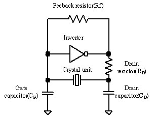
◎石英晶體之電氣迴路設計(一)
由於石英震盪迴路具有控制頻率穩定性高之特點,其頻率控制變化量單位為百萬分之一(ppm)。
且石英晶體具有高Q值特性,只要微小的驅動就能持續震盪。
一般電氣迴路設計利用典型回饋放大器,利用兩端電容分壓,一端輸入,一端輸出,使晶體持續震盪之設計。
但這樣的設計需注意兩點;
(一)振幅條件:Re≦|Ri| (Ri是負的電阻,3~10X Re)
(二)相位條件:ωLe – 1/ωCi=0
相位條件是由等值輸入電容來決定,同時也是決定震盪頻率的條件,
而振幅條件則是震盪啟動及能正常持續震盪的條件。
通常把Ci稱為迴路上的負載電容CL,是決定頻率可變範圍、感度及頻率穩定度的重要參數。
下圖中顯示為震盪迴路常用元件說明,
(1)
Oscillation circuit constant guide
|
Frequency range
|
Rf(MΩ)
|
RD(KΩ)
|
CG(pF)
|
CD(pF)
|
|
20~60KHz
|
20
|
500
|
10
|
10
|
|
60~165KHz
|
20
|
300
|
10
|
10
|
|
5.5~30MHz(Fund)
|
1
|
0.5
|
5~15
|
5~15
|
|
30~50MHz(Fund)
|
1
|
0.5
|
5~10
|
5~10
|
|
 |
Inverter:Toshiba TC74HCU04(Unbuffer) or similar product. However, for the 30~50MHz frequency range.
Toshiba TC74HCU04(Unbuffer) or similar product is used.
|
※ refer to Epson toyocom website
(2)
Oscillation circuit constant guide
|
Frequency range
|
Rf(MΩ)
|
RD(KΩ)
|
CG/ CD(pF)
|
Load capacitance (pF)
|
|
3~4MHz
|
1
|
4.7
|
33
|
20
|
|
4~5MHz
|
1
|
3.3
|
33
|
20
|
|
5~6MHz
|
1
|
2.2
|
33
|
20
|
|
6~9MHz
|
1
|
1.0
|
22
|
16
|
|
9~10MHz
|
1
|
0.47
|
22
|
16
|
|
10~15MHz
|
1
|
0.47
|
15
|
12
|
|
15~20MHz
|
1
|
0.47
|
15
|
12
|
|
20~25MHz
|
1
|
0.47
|
10
|
10
|
Inverter:
Toshiba TC74HCU04AP(Unbuffer) or similar product.
|
(3)Overtone oscillation circuit
Oscillation circuit constant guide
|
Frequency range
|
RD(Ω)
|
C1(pF)
|
C2(pF)
|
L1(uH)
|
CL(pF)
|
|
30~40MHz
|
820
|
10
|
18~10
|
2.2
|
10
|
|
40~50MHz
|
470
|
7
|
15~10
|
1.5
|
8
|
|
50~60MHz
|
330
|
5
|
15~10
|
1.0
|
8
|
Inverter:Toshiba TC7SHU04(Unbuffer) or similar product.
|
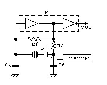
◎石英晶體之電氣迴路設計(二)
Ø Measure method of negative resistance:
Connect the pure resistor (Rs shown in Figure 1) with series to crystal, increase the resistance value step by step, and obtain the resistance value right before the oscillation stops indicates the negative resistance of the circuit. Confirm oscillation at the buffer output t (or crystal terminal) by using oscilloscope. Since the negative resistance changes by temperature and supply voltage, it is necessary to change temperature with coolant spray and heat gun add also to repeat cheeking whether supply voltage is on or off.
Negative Restance (-R) = Rs+RR
RR:ESR value of the crystal used for measuremt
Ø Measure method of Driv Level:
Measure electric current value of the crystal by using electric current probe and obtain the crystal oscillator current.
|
Level of drive=I2 * RL
RL=R1 * (1+C0/CL)2
RL:Loadded resonance resistance
R1:Resistance of crystal unit
I:Current flow into crystal unit
C0:Shunt capacitance
CL:Load capacitance
|


.jpg)
.jpg)
.jpg)
.jpg)